In-Circuit Test (ICT) Buyer’s Guide for PCB Assemblies
In-circuit test verifies PCB assembly functionality by probing components on the board. This guide covers fixture types, test coverage, and selection criteria to help buyers ensure reliable functional verification before shipment.
- In-circuit test uses a physical fixture to probe components directly on the populated board.
- Fixture design determines which components are accessible and how the test is structured.
- Test coverage depends on board complexity, component type, and fixture cost.
- A clear test strategy aligns ICT with other inspection methods like AOI and X-ray.
- Validate fixture performance with sample boards before committing to production runs.
In-circuit test, or ICT, connects a test system directly to a populated PCB to verify electrical function. It sits between automated optical inspection and field testing in the assembly line. For buyers specifying test coverage, understanding fixture mechanics and test limits prevents gaps that surface after shipment.
What is in-circuit test and how does it work?
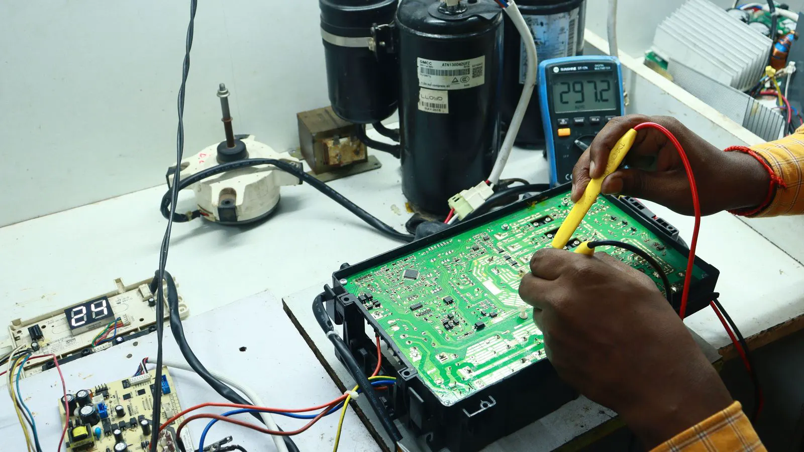
An in-circuit test system uses a fixture to make physical contact with the board. The fixture holds the PCB and routes test signals to specific points. The test system then measures parameters like resistance, continuity, and component behavior.
The fixture is the defining feature of ICT. It determines which components are accessible. A board with dense bottom-side components may need a lift-off probe or a backside test fixture. A board with tall connectors may require a custom fixture that clears those parts.
The test itself is usually script-driven. The system runs a test program that checks predefined parameters. For a power module, this might include checking that a MOSFET switches correctly, that a regulator holds its output voltage, and that no short exists between power rails. For a control board, it might verify that a microcontroller responds to a reset signal and that a sensor returns a plausible value.
What fixture types are available for in-circuit test?
Fixture design is the most variable part of ICT. The fixture must hold the board securely while exposing enough points for testing. Different fixture types suit different board geometries.
| Fixture Type | Typical Use | Trade-Off |
|---|---|---|
| Top-side probe | Boards with accessible top-side components | Cannot test bottom-side components unless lifted |
| Bottom-side probe | Boards with critical bottom-side components | Requires access to the backside |
| Lift-off probe | Boards where components block direct probe access | More complex fixture, higher cost |
| Boundary scan | Boards with JTAG-enabled ICs | Limited to ICs that support boundary scan |
| Custom mechanical fixture | Boards with unusual shapes or tall components | Highest cost, longest lead time |
Top-side fixtures are the most common. They sit on the top surface of the PCB and probe through the board material. They work well when the critical test points are on the top side or when bottom-side components are not essential for functional verification.
Bottom-side fixtures require the board to be flipped or the fixture to reach underneath. This adds handling time and can introduce stress on tall components if the fixture is not designed carefully.
Lift-off fixtures use a mechanical arm or pneumatic system to raise components out of the way. This is common for boards with capacitors or connectors that block probe access. The fixture is more complex and costs more, but it enables testing of points that would otherwise be inaccessible.
Boundary scan is a different approach. Instead of probing each pin, it uses the IC’s built-in test logic to shift data through the boundary pins. This is faster and requires fewer probe points. It is not available for every IC, and it may not test all internal functions.
How do you evaluate test coverage for a PCB assembly?
Test coverage is the percentage of components or functions that the ICT program verifies. A high coverage number sounds good, but the meaning depends on what is actually being measured.
The first step is to define the test objectives. For a power supply, the goal is to confirm that the output voltage is correct and that the board does not draw excessive current. For a communication module, the goal is to verify that the radio transmits and receives at expected signal levels. For a safety-critical control board, the goal may include checking that safety interlocks open and close correctly.
The second step is to map test points to components. Some components are easy to test with a simple resistance check. A resistor should show a value within tolerance. A diode should show forward voltage in one direction and block current in the other. A capacitor should show the expected impedance at a test frequency.
Other components require active testing. A microcontroller may need to be powered and have its firmware loaded to confirm it boots correctly. A sensor may need to be exposed to a stimulus, such as light or temperature, to verify that its output changes within expected bounds.
The third step is to consider the test environment. ICT is usually done in a controlled environment, but environmental factors can affect results. A board tested at 25 degrees Celsius may behave differently at the lower end of its operating range. If the application operates at extreme temperatures, the test program should include a thermal soak or a cold-soak step.
The fourth step is to review the test program documentation. A good test program should list each test, the pass/fail criteria, and the expected result. It should also note any known limitations, such as components that are not tested due to fixture constraints.
How does ICT compare to AOI and X-ray inspection?
In-circuit test is a functional test. It verifies that the board does what it is supposed to do. AOI and X-ray are inspection methods. They verify that the board is built correctly.
AOI checks solder joint quality, component placement, and missing parts. It uses cameras and image processing to detect defects like bridging, tombstoning, and incorrect orientation. AOI is fast and non-contact, but it cannot verify that a component functions correctly. A perfectly soldered resistor can still be out of tolerance.
X-ray inspection looks inside the board. It detects buried solder joints under components and checks for voids in BGA solder balls. It is non-destructive and does not require probe access. However, it is expensive and does not test electrical function.
ICT fills the gap between inspection and function. A board can pass AOI and X-ray and still fail to operate. A board can pass ICT and still have a cosmetic defect that does not affect function. For many applications, all three methods are used in sequence. AOI catches placement and solder defects. X-ray catches hidden defects. ICT verifies function.
The choice depends on the risk profile of the application. A consumer product with a simple control board may use AOI and a basic ICT. A medical device board may use AOI, X-ray, and a detailed ICT program that includes stress tests. A high-reliability industrial board may include a full system-level test in addition to ICT.
What are the common mistakes when specifying in-circuit test?
The most common mistake is treating ICT as a black box. Buyers often specify a test coverage percentage without understanding what that percentage means. A 90 percent coverage rate could mean 90 percent of resistors are checked, or it could mean 90 percent of board functions are verified. The difference matters.
Another mistake is not accounting for fixture access. A board with a dense array of components on the bottom side may not be testable with a standard top-side fixture. If the fixture does not reach the critical points, the test program will miss them. This is often discovered during fixture qualification, after the fixture has been built. The cost to redesign the fixture is high.
A third mistake is not validating the test program against known-good and known-bad boards. The test program should be run against boards that are confirmed good and boards with known defects. This confirms that the test detects the defects it is supposed to catch and that it does not flag good boards as bad.
A fourth mistake is ignoring the test environment. If the test is run in a cold room, the results may differ from the results at room temperature. If the board is tested under load, the results may differ from a no-load test. The test environment should match the operating environment as closely as practical.
A fifth mistake is not planning for test program updates. When a board is revised, the test program must be updated. If the test program is not version-controlled, the wrong version may be run on the wrong board revision. This causes false failures or missed defects.
How do you select a test provider or build an in-house ICT capability?
The decision depends on volume, complexity, and quality requirements. For low-volume or prototype boards, an in-house ICT setup may be cost-prohibitive. A test provider can handle the fixture design and test execution. For high-volume production, an in-house capability may be justified by the cost savings and the control over test data.
When selecting a test provider, ask for the fixture design process. A good provider will start with the board layout and the test objectives to design the fixture. They will provide a test point map and a test program before building the fixture. They will also provide a qualification report that shows the fixture working on sample boards.
When building an in-house capability, the main costs are the test system, the fixture, and the engineering time to develop the test program. The test system can range from a basic multimeter-based unit to a complex system with multiple channels and automated fixtures. The fixture cost depends on the board complexity. The engineering cost depends on the test program complexity.
The test data is as important as the test results. A good ICT setup records the results for every board, every component, and every test. This data can be used to track defect trends, identify root causes, and verify that the test program is catching the defects it is supposed to catch.
What should be included in a final in-circuit test specification?
A clear specification reduces ambiguity and improves consistency. The specification should include the following elements.
- Test objectives and pass/fail criteria for each function.
- List of components to be tested and the type of test for each.
- Fixture requirements, including access points and clearances.
- Test environment conditions, such as temperature and voltage.
- Test sequence and timing for each test.
- Data logging requirements, including what data to record and where to store it.
- Qualification procedure, including how the fixture and test program will be validated.
- Revision control process for test program updates.
The specification should also note any components that are not tested and the reason why. If a component is not tested because it is blocked by another component, the specification should state that clearly. This prevents surprises during production.
A final review of the specification with the assembly line and the test engineering team helps identify gaps before the fixture is built. The more details are in the specification, the fewer questions arise during fixture qualification.
Decision checklist for in-circuit test selection
Use this checklist to evaluate your ICT requirements before committing to a fixture or a test provider.
- Are all critical functions on the board accessible to the fixture?
- Does the test program cover all required functions, or are there gaps?
- Is the fixture design approved by the board design team?
- Has the test program been validated against known-good and known-bad boards?
- Are the test environment conditions documented and reproducible?
- Is the test data logged and stored for traceability?
- Is there a process for updating the test program when the board is revised?
- Is the test cost justified by the risk profile of the application?
- Has the fixture been qualified for the expected production volume?
- Are the pass/fail criteria clear and unambiguous?
In-circuit test is a practical way to verify that a PCB assembly works before it leaves the factory. The fixture determines what can be tested. The test program determines what is measured. The specification ties the two together. A well-defined ICT program reduces field failures and gives buyers confidence that the board performs as designed.
Frequently asked questions
Can in-circuit test detect solder defects?
ICT can detect some solder defects, such as shorts or open circuits, but it is not a substitute for AOI or X-ray. AOI and X-ray are better for detecting solder joint quality and hidden defects.
How long does it take to build an in-circuit test fixture?
Fixture build time depends on board complexity and access requirements. A simple top-side fixture may take a few weeks. A complex fixture with lift-off probes or bottom-side access may take longer.
Is in-circuit test destructive to the board?
No. ICT is a non-destructive test. The fixture probes the board without altering it. However, the fixture must be designed carefully to avoid damaging components during handling.
Can in-circuit test be used for prototype boards?
Yes, but the fixture cost may be high relative to the prototype volume. For prototypes, a manual test setup or a basic fixture may be more practical.
What is the difference between in-circuit test and system-level test?
ICT tests the board in isolation. System-level test tests the board as part of a larger system, including other boards and components. System-level test is more comprehensive but also more complex and expensive.