How to Read an AOI Report and Triage PCB Defects
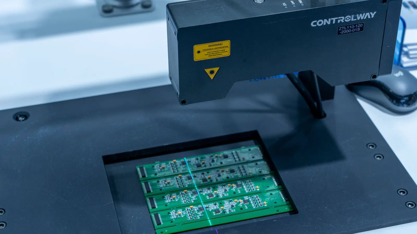
An AOI report maps automated optical inspection findings against design rules. Interpreting it correctly separates minor cosmetic issues from critical defects. This guide explains how to read flags, verify defects, and triage boards efficiently.
- An AOI report provides a map of detected anomalies, not a final verdict on every single part.
- Severity levels and defect categories must be cross-referenced with the design ruleset.
- Human verification is required to distinguish between real defects and false positives.
- Triage decisions should prioritize safety-critical and functional failures over cosmetic issues.
Prerequisites Before Opening the Report
An AOI report is a data file, not a standalone document. You cannot effectively triage defects without the right context.
Gather the board design file or the golden reference used during the inspection run. Without this, you cannot verify if a detected issue is real. Also, have the assembly work instructions or the Bill of Materials on hand. You need to know which components are critical. A power stage MOSFET carries different risk than a small signal resistor. Knowing which parts are critical lets you prioritize your time.
Check the software version and the inspection recipe. A recipe tuned for a dense surface mount device board will flag differently than one used for through-hole boards. If the recipe changed, the noise levels will change. A recipe set for a 0402 capacitor will flag a different amount of solder blob on a 0805 component. If the recipe changed between runs, the noise levels will change.
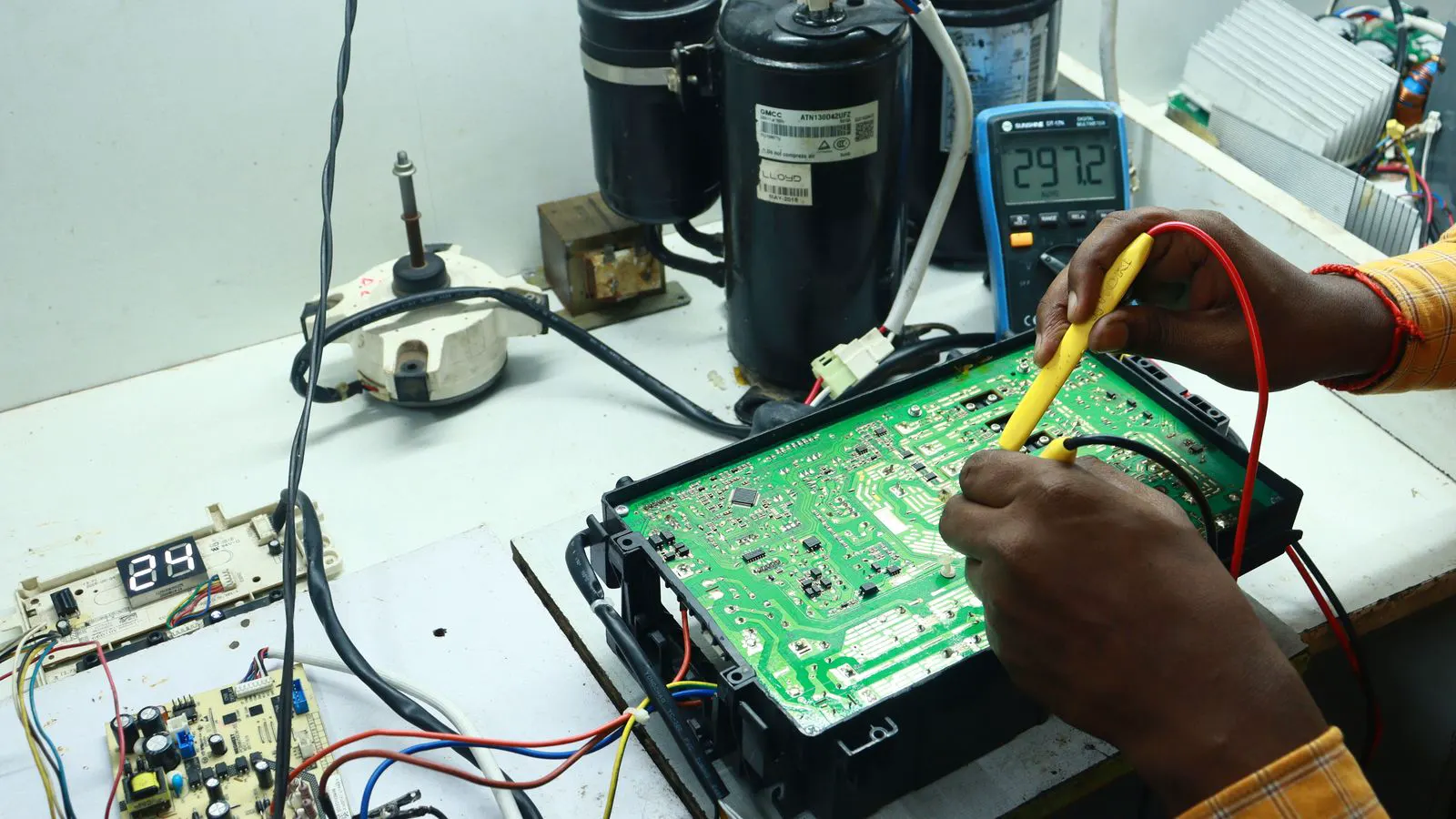
Ensure you have access to the physical board. Digital reports are only half the story. You need a microscope or a high-magnification camera to verify findings. A digital image cannot always distinguish between a solder blob and a solder bridge. You need to see the physical reality to make a final call.
Step-by-Step Guide to Reading the AOI Report
-
Open the summary view first.
Do not jump into the image grid. Look at the dashboard or summary page. It lists the total number of defects, the pass/fail count, and the breakdown by severity.
Reason: This gives you the overall health of the batch. If 50% of boards failed, the issue is likely systemic, not random. Look at the trend line. If the defect count spikes at the beginning of the run, the placement machine may not have calibrated properly. If the count is steady, the process is stable. -
Filter by defect severity.
Most AOI software categorizes findings as critical, major, or minor. Start with critical defects. These usually involve missing components, short circuits, or reversed polarity.
Reason: These items pose immediate risk. If a critical defect exists, the board is likely scrap or requires immediate rework before further testing. Do not spend time analyzing minor tilt errors if a power IC is missing. -
Review the defect list for each failing board.
Each entry should show a coordinate or component reference designator. It will also list the defect type, such as “Solder Bridge” or “Missing Part.”
Reason: This helps you group similar issues. If five boards all fail on the same reference designator, the problem is likely in the placement or pick-and-place process, not the inspection itself. Check if the reference designator is near the edge of the placement area. Placement accuracy often drops near the machine boundary. -
Zoom into the flagged image.
Click the defect to view the captured image. Compare the actual image against the golden reference image provided in the software.
Reason: The software detects pixel differences. Your job is to determine if that difference is a physical defect or a lighting artifact. Look at the shadow. If the shadow moves with the component, the component is tilted. If the shadow stays, the component is flat. -
Check the confidence score.
Many systems assign a percentage to each detection. High scores indicate the software is certain. Low scores are often false positives.
Reason: Low-confidence flags require more scrutiny. They are frequently caused by shadows, reflective surfaces, or component tilt within acceptable limits. A 40% confidence flag on a shadow is not a defect. A 95% confidence flag on a missing resistor is almost certainly a defect. -
Cross-reference with the design rule set.
Some defects are acceptable by design. For example, a slight tilt might be within specification. Check the inspection recipe settings to see what tolerances are allowed.
Reason: Strict rules create noise. Understanding the tolerances prevents you from rejecting good boards. If the recipe allows 2 degrees of tilt, a 1.5 degree tilt is a pass. If the recipe allows 0.5 degrees, a 1.5 degree tilt is a fail. -
Verify the defect physically.
Take the board to the bench. Use a microscope to inspect the flagged area. Look for actual solder bridges, missing pads, or damaged components.
Reason: Automated systems cannot always distinguish between a solder blob and a solder bridge. Physical verification is the final check. Look for a continuous metal path between the pads. If there is no path, it is a blob, not a bridge. -
Classify the defect for triage.
Based on your verification, assign the board a disposition: pass, rework, or scrap. Document the reason.
Reason: Accurate classification feeds back into quality metrics and helps identify root causes over time. If you classify a solder bridge as scrap, you miss the chance to rework it. If you classify a missing component as pass, you send a bad board to test. -
Log the findings in the quality system.
Record the defect type, the component, and the action taken. Use standardized codes.
Reason: This data is essential for trend analysis. If a specific defect type spikes, you need to know when and where it happened. If “Missing Part” spikes on Board A, check the feeder for that component. If “Solder Bridge” spikes on Board B, check the stencil.
Common Mistakes in AOI Report Interpretation
Technicians often make errors that lead to incorrect triage decisions.
Ignoring false positives.
If you reject every flag, your scrap rate will be high. Many flags are artifacts. Learning to spot common false positives, such as shadows on matte components, saves time and money. A shadow on a black resistor looks like a missing part in a low-resolution image. Zoom in. If the shadow is consistent, it is not a defect.
Over-trusting the software.
The AOI system is a tool, not a judge. It lacks context. It does not know if a component is functional. It only sees pixels. A component can be present but not soldered. The AOI sees the component. It does not see the lack of solder. You need to check the joint.
Skipping the physical verification step.
Digital reports are fast. Physical inspection is slower. Cutting this corner leads to bad boards shipping to customers. A digital image can hide a cracked joint. A microscope reveals it. Do not skip the step.
Ignoring the pattern.
A single defect is an anomaly. A cluster of defects is a signal. If the same type of defect appears on multiple boards, stop and investigate the process. If “Solder Lift” appears on five boards, the solder paste may be too dry. If “Missing Part” appears on five boards, the feeder may be empty.
Understanding Defect Types
AOI reports use specific terminology. Knowing these terms speeds up triage.
| Defect Type | Description | Typical Cause |
|---|---|---|
| Solder Bridge | Excess solder connecting two pads or pins | Wetting issue, too much paste |
| Missing Part | Component not present at expected location | Placement error, component shortage |
| Solder Lift | Pad or component lifted off the board | Thermal shock, poor adhesion |
| Component Tilt | Part not aligned with reference | Placement accuracy issue |
| Shadow | Dark area not part of the component | Lighting angle, high-profile part |
Final Verification Step
After you have triaged the defects, perform a final check on the rework or rejected boards.
If a board was reworked, re-inspect the specific areas that were fixed. Do not just assume the repair is good. Run a spot check or full AOI pass on the reworked section. If you reworked a solder bridge, check for new bridges. If you reworked a missing part, check for tilt.
If a board was rejected, log the reason. Keep the board for trend analysis if possible. A rejected board is a physical sample of the problem. Keep it. It helps the root cause analysis.
This final step closes the loop. It ensures that the triage decision was accurate and that the board is safe for its next stage.
When to Escalate
Not all defects are the same. If you encounter a defect that is not in your reference list, or if a defect causes a functional failure, escalate it.
Bring the board, the report, and the design file to a senior engineer. They can determine if the defect is a manufacturing issue, a design issue, or a test issue. If the AOI flags a “Solder Bridge” but the functional test passes, it may be a false positive. If the AOI passes but the functional test fails, the AOI may be missing a defect.
Do not guess. Escalation prevents incorrect repairs and protects product quality. A guess can lead to a bad repair. A senior engineer can see the whole picture.
Frequently asked questions
Can I skip physical verification for minor defects?
No. Even minor defects can indicate a larger process issue. Verify a sample of minor defects to ensure they are not actually critical.
How do I handle a high number of false positives?
Review the inspection recipe. Adjust lighting or tolerance settings. Work with your AOI vendor to fine-tune the detection parameters.
What is the difference between a major and minor defect?
A major defect affects function or reliability. A minor defect is cosmetic or within specification. Check your internal quality standards for definitions.
Should I keep the AOI report for every board?
Yes. Keep the digital file for every board, especially those that failed. This data is critical for audits and trend analysis.
How often should I update the golden reference?
Update it whenever the design changes. If the assembly process changes significantly, review the reference to ensure it matches current production conditions.