Troubleshooting: Preventing Component Shifting in SMT
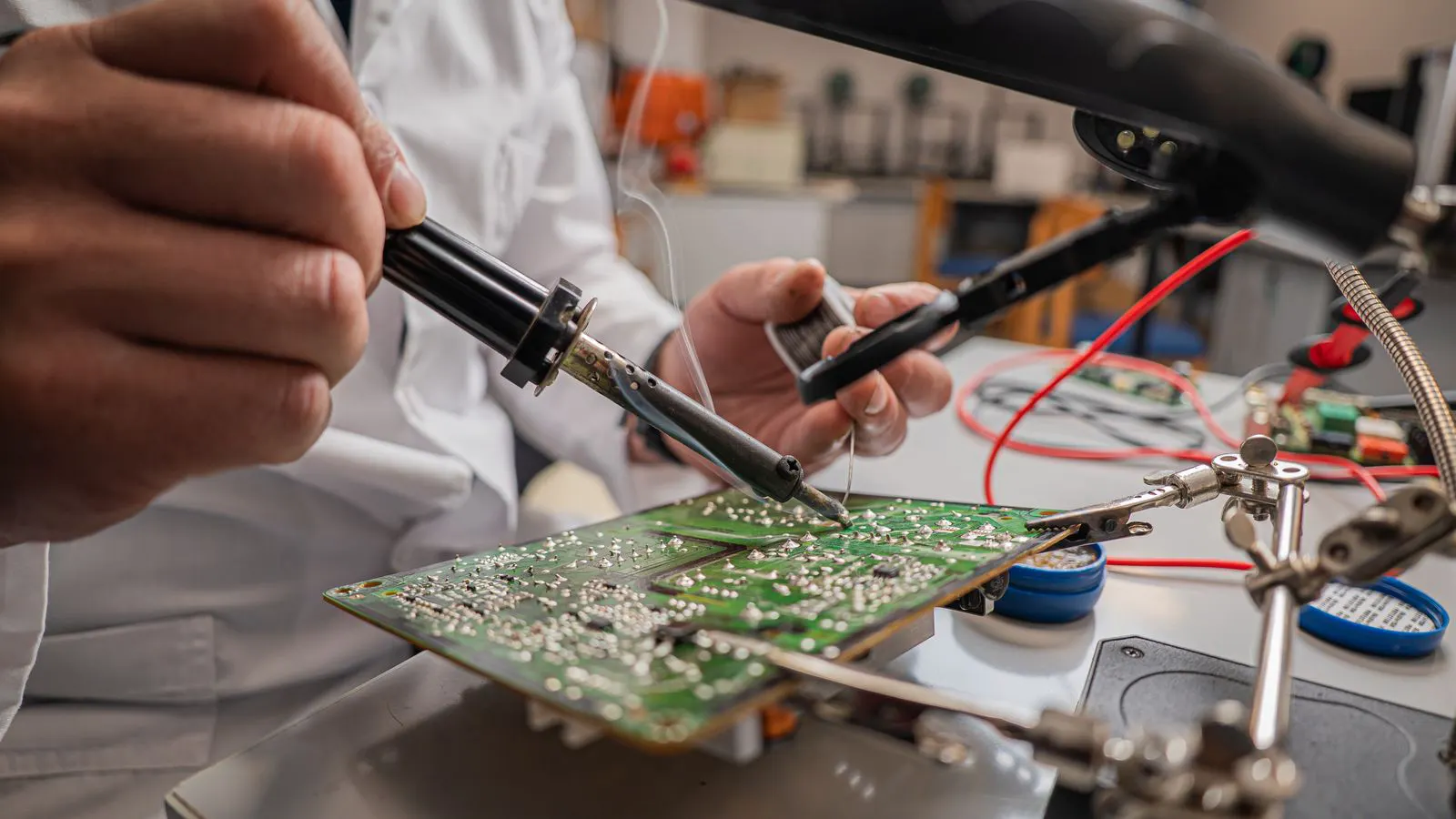
Component shifting causes solder bridging and misalignment. Prevent it by checking solder paste viscosity, placement accuracy, reflow profile, and component handling. Use the table below to match symptoms to fixes.
- Check solder paste viscosity and stencil thickness before running production.
- Verify placement accuracy and downforce settings on the pick-and-place machine.
- Review the reflow profile to avoid excessive liquid time that allows parts to move.
- Inspect board handling and carrier design for vibration or tilt during transport.
- Use pre-soldering or tack solder for components prone to shifting in complex layouts.
Why Components Shift During SMT Assembly
Component shifting happens when parts move after solder paste is applied but before the solder joint solidifies. This movement can pull a component off its footprint, create bridging, or leave the part tilted. The result is a defective board that fails electrical tests or creates a long-term reliability risk.
Shifting is most common on small surface mount devices, such as 0402 capacitors, resistors, and thin film transistors. These parts have low mass and small solder pads. Any vibration, air movement, or uneven heating can displace them. Larger components, such as power modules and connectors, are less likely to move, but they can shift if the solder paste volume is excessive or the reflow profile is too aggressive.
The problem usually appears at one of three stages: solder paste application, component placement, or reflow soldering. Identifying where the movement starts is the first step to fixing it.
Common Symptoms of Component Shifting
| Symptom | Likely cause | What to do |
|---|---|---|
| Component tilted or rotated after reflow | Solder paste volume too high, or placement downforce uneven | Reduce paste deposit, verify placement downforce, check stencil condition |
| Solder bridging between pads | Component moved onto adjacent pad, or paste applied too thickly | Reduce paste thickness, improve placement accuracy, add solder mask over bridges |
| Component missing from footprint | Part moved off the board during handling or reflow | Inspect board carrier, reduce vibration, use tack solder or pre-soldering |
| Part shifted but still functional | Minor movement during liquid phase, often from fast ramp | Adjust reflow profile to shorten liquid time, stabilize board during heating |
| Repeated shifting on the same footprint | Poor pad wetting, or component footprint mismatch | Check pad finish, verify design rule, reflow with corrected profile |
| Shifting only at line end | Air flow from conveyor or operator handling | Shield reflow zone, use enclosed carriers, standardize handling procedure |
These symptoms do not always point to a single cause. A tilted 0402 part, for example, may result from a worn stencil that leaves extra paste on the edge. The same part can shift if the placement machine applies uneven pressure. You need to isolate the stage where the movement begins.
Solder Paste Application as a Cause
Solder paste is the primary holding agent for surface mount components before reflow. If the paste volume is too high, the part has more material to move through. If the paste is too thin, it may not hold the part at all. Both extremes create shifting risk.
Stencil thickness is the main variable. A thicker stencil deposits more paste. A thinner stencil deposits less. Many facilities use 125 microns or 100 microns for standard components. For fine-pitch parts, 80 microns or 95 microns is more common. If the stencil is worn, clogged, or misaligned, the deposit can vary across the board. This creates uneven paste heights and uneven holding forces.
Paste viscosity also matters. A paste that is too wet flows too easily during handling. A paste that is too thick may not spread properly, leaving the part on a small peak of material. Both conditions make the part easier to move.
Check the stencil after each run. Clean it with a proper stencil cleaner. Inspect the copper mesh for tears. Replace the stencil when the aperture edges are rounded or the mesh is deformed. Measure the paste deposit with a microscope or a paste thickness gauge. Compare the reading to your process specification.
Component Placement Accuracy and Downforce
Placement machines apply a consistent downforce to press components into the paste. If the downforce is too low, the part does not press into the paste. It sits on top. If the downforce is too high, it can smear the paste or damage fine-pitch parts. Both conditions increase shifting risk.
Placement accuracy is the second factor. If the machine places the part slightly off-center, the paste is compressed unevenly. The part may tilt during reflow. The machine camera and fiducial points must be calibrated. Check the calibration before running a new board type. Verify that the placement offset is within tolerance.
For small parts, the placement nozzle must be clean. A partially clogged nozzle can deposit the part unevenly. A worn nozzle can drop the part with a slight impact. Inspect nozzles regularly. Replace them when the aperture is worn.
If a part shifts only on a specific footprint, check the placement map. Look for a small offset in the X or Y axis. Look for a rotation angle. The machine may be compensating for a fiducial error. Re-calibrate the machine and re-run the placement.
Reflow Soldering and Liquid Phase Time
The reflow profile is where component shifting often becomes visible. The liquid phase is the window when the solder is molten but the board has not fully solidified the joint. If this phase is too long, the part has time to move. If the board is tilted or vibrated during this window, the part will shift.
The ramp rate affects how quickly the board enters the liquid phase. A slow ramp keeps the board in the pre-solder state longer. This gives the operator or machine more time to handle the board. A fast ramp shortens the liquid phase. It also reduces the time for the paste to flow.
The peak temperature must be high enough to wet the pads and form a good joint. A peak that is too low may not fully wet the pads. The part may appear shifted even if it did not move. A peak that is too high may cause the part to jump or the solder to ball.
Review the reflow profile for each board type. For fine-pitch parts, a shorter liquid phase is preferred. For larger components, a longer liquid phase may be acceptable. Use the data logger readings from the production run. Compare the actual profile to the target. Adjust the oven zones or conveyor speed to match.
Board Handling and Carrier Design
Shifting can also happen outside the reflow oven. A board that is tilted during transport can move components before they enter the oven. A board that is bumped on a conveyor can shift parts after placement but before reflow.
Board carriers and trays must hold the board flat. A warped tray or a loose carrier creates gaps. The board can rock. This rocking moves small parts. Use a carrier that supports the board at multiple points. Avoid carriers that lift only the edges.
Air flow from the conveyor or from nearby equipment can push light parts. Shield the placement and reflow areas from drafts. Use enclosed carriers where possible. Standardize handling procedures. Operators should lift boards from the same side. They should avoid holding boards by the edges where components are exposed.
For boards with dense small parts, consider a pre-soldering step. Tack solder the parts in place before final reflow. This holds the part on the footprint. It reduces the chance that a vibration or handling error will move it. Pre-soldering adds a step, but it can save a high-value board from a shifting defect.
Prevention Tips for Reliable SMT Assembly
- Measure solder paste deposit height before production. Compare to the process specification. Adjust the stencil or paste thickness as needed.
- Calibrate the placement machine before each board type. Verify downforce and placement accuracy.
- Inspect the stencil after each run. Clean it. Replace it when the mesh is worn.
- Review the reflow profile. Shorten the liquid phase for fine-pitch parts.
- Use a board carrier that supports the board flat. Shield the process area from air flow.
- Standardize operator handling. Lift boards from the same side. Avoid tilting.
- Use tack solder or pre-soldering for high-risk layouts.
- Keep placement nozzles clean. Replace worn nozzles.
- Check fiducial points on the board. Ensure the machine sees them correctly.
- Log reflow data. Compare actual profiles to target profiles.
These steps do not require expensive equipment. They require discipline. Measure what you can. Check what you should. Adjust what you need. Component shifting is a process problem. Fix the process and the defect stops.
When to Escalate a Shifting Issue
If a shifting issue appears on multiple board types, the cause is usually upstream. Check the solder paste lot. Check the stencil condition. Check the placement machine calibration. If the issue appears on one board type only, the cause is usually the design or the profile. Check the footprint size. Check the component mass. Check the reflow profile.
If the issue persists after these checks, look at the board material. A flexible board can bow during reflow. A board with a thin copper layer can flex under the heat. These materials can move components even when the paste and placement are correct. Use a rigid carrier or a pre-bent support. Adjust the profile to reduce thermal stress.
Document the issue. Take a photo of the shifted part. Record the board type, the component part number, the paste lot, the stencil number, and the reflow profile. Share the data with the process team. A clear record makes it easier to isolate the cause.
Component shifting is a common defect. It is also a predictable one. The parts move when the solder is liquid. They move when the board is not flat. They move when the paste is not holding them. Fix the paste. Fix the placement. Fix the profile. Fix the handling. The parts stay where they belong.
Frequently asked questions
How do I know if a component shifted during placement or during reflow?
Check the board before reflow. If the part is already off-center, the placement machine or handling caused the move. If the part is correct before reflow but shifted after, the liquid phase or board handling caused the move.
What is the best stencil thickness for small parts?
For 0402 and smaller parts, use 80 microns or 95 microns. For larger parts, use 100 microns or 125 microns. Match the thickness to the paste specification and the component footprint.
Can I prevent shifting with a faster reflow ramp?
A faster ramp shortens the liquid phase. This reduces the time the part can move. It does not prevent shifting if the paste is too thin or the board is tilted. Use it as one part of the fix, not the only fix.
Is tack solder a permanent solution?
Tack solder holds the part in place during handling and reflow. It is useful for high-value boards or dense small parts. It adds a step and may not be needed for standard production.
What should I check first if a small part keeps shifting?
Check the solder paste deposit height. Then check the placement downforce. Then check the reflow liquid phase time. These three factors cause most shifting issues.