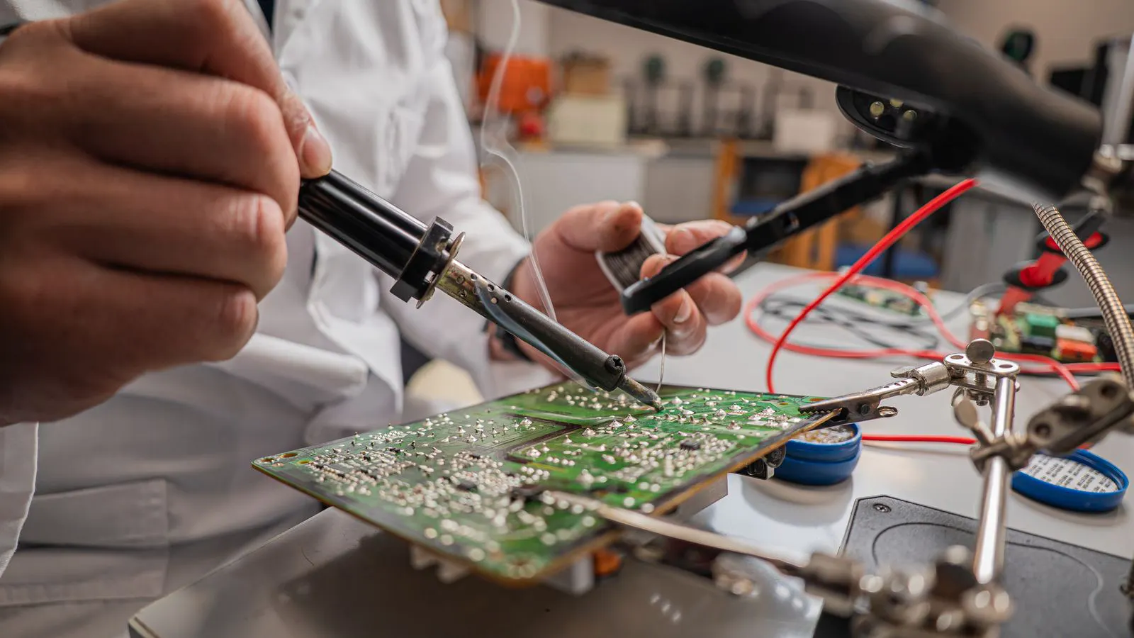
Outlook: Advanced Soldering Methods for PCBA

Advanced soldering methods are changing how PCBA teams handle fine pitch, high density, and mixed technologies. This outlook covers five practical shifts buyers should plan for, from paste selection to inspection strategy, and explains how to prepare your supply chain.
- Fine pitch and large components are pushing soldering beyond standard reflow profiles.
- Buyers need to align paste, stencil, and inspection choices with the actual board mix.
- Mixed assembly lines require documented process controls and clear capability statements.
- Supplier documentation should include process windows, known failure modes, and verification records.
- Planning for hybrid and multi-stage assembly reduces the risk of rework and yield loss.
Soldering remains the core mechanical and electrical step in PCBA production. But the mix of components, substrates, and design rules has changed enough that older assumptions about reflow, paste, and inspection no longer cover every case. Buyers and engineers need a practical view of where soldering is heading and what preparation looks like on the floor.
What is driving the shift in soldering technology?
Several forces are working in the same direction. Component sizes keep shrinking while board density increases. Thermal management and power delivery push designs toward thicker copper, larger heat sinks, and higher current paths. Mixed technologies are common on a single board, such as fine pitch surface mount, through-hole connectors, and large power components.
This combination creates a problem for standard practice. A single reflow curve that works for a general consumer board often fails on a mixed board. A paste that spreads cleanly for a QFN may bridge on a 0402 capacitor. A stencil aperture that clears a BGA ball may clog on a fine pitch IC.
The result is a move away from one size fits all. Soldering methods are becoming more specialized. Teams are designing processes around specific failure modes rather than relying on generic settings.
How is reflow and selective soldering changing?
Traditional reflow soldering remains the workhorse for high density SMT. But its limits are showing in areas with large thermal mass, mixed geometries, or high reliability requirements. Selective soldering, where only selected joints are heated, is gaining traction in mixed assembly.
Selective reflow allows a team to hold a large connector at a lower temperature while a fine pitch IC on the same board receives a higher peak. This reduces stress on through-hole components and lowers the risk of component cracking or solder migration. It also gives inspectors a clearer view of the joints that matter most.
The trade-off is complexity. Selective soldering requires more fixtures, more process windows, and more verification. It is not a drop-in replacement for standard reflow. It is a targeted tool for boards where standard reflow would force compromises.
Buyers should ask suppliers which joints are handled by reflow and which are handled selectively. The answer changes the risk profile. It also changes the inspection plan, because selective joints may have different thermal history than reflowed joints.
What role does paste and stencil management play?
Solder paste selection is no longer a simple viscosity choice. Paste chemistry, flux profile, and particle size interact with board geometry and component finish. A paste that works for a matte tin plating may bridge on a fine pitch IC. A paste that clears a BGA ball may not wet a small SMD resistor.
Stencil aperture geometry is the second variable. Aperture size, aspect ratio, and edge profile determine how much paste lands on each pad. A small aperture reduces bridge risk but increases clog risk. A larger aperture improves paste volume but increases bridge risk. The right choice depends on the pad size, the component footprint, and the solder alloy.
The practical shift is toward tighter control of these variables. Teams are tracking paste expiry, stencil wear, and aperture dimensions more rigorously. They are also aligning paste selection with the actual component mix rather than a generic BOM.
For buyers, this means asking for the paste and stencil data behind a specific board, not just a generic capability statement. A supplier that can explain why a particular paste works for a particular component mix is in a better position to hold yield.
How is inspection adapting to new soldering methods?
X-ray inspection remains the standard for BGA and other hidden joints. But the scope of inspection is expanding. Teams are moving from random sampling to targeted inspection based on known failure modes. A board with a large power connector may need X-ray on the through-hole joints. A board with a fine pitch IC may need optical inspection for bridge or tombstone defects.
Automated optical inspection continues to improve, but it still struggles with small components and dense footprints. X-ray is better for hidden joints but less effective for some surface defects. The trend is toward combining both, with a clear decision matrix on which joints get which check.
The inspection strategy should match the soldering method. If a board uses selective reflow, the inspection plan should account for the different thermal history of those joints. If a board uses a high temperature alloy, the inspection should look for specific failure modes associated with that alloy.
Buyers should ask for the inspection plan before finalizing a production run. A generic inspection report is not enough. The plan should show which joints are checked, how they are checked, and what the acceptance criteria are.
How are suppliers responding to these changes?
Suppliers are splitting into two groups. One group is expanding its capability to handle complex, mixed-technology boards. These teams invest in selective reflow, advanced X-ray, and tighter process controls. The other group is staying focused on high volume, standard SMT.
This is not a bad thing. It is a natural market adaptation. A supplier that can handle a dense, mixed board may not be the best choice for a high volume consumer product. A supplier that specializes in high volume may not be the right fit for a small batch of high reliability boards.
The key for buyers is clarity. A supplier should be able to state what it does well, what it does not do, and how it verifies the work. A capability statement that covers everything is less useful than a clear statement that covers the specific board in question.
What should buyers plan for in the next cycle?
Five shifts deserve attention. First, mixed technology assembly will become more common. Boards will combine fine pitch SMT, through-hole components, and large power devices on the same substrate. This requires more detailed process planning.
Second, selective soldering will grow in use. It is not a replacement for reflow, but it is a useful tool for boards where standard reflow would force compromises. Buyers should be comfortable specifying which joints need selective treatment.
Third, paste and stencil management will matter more. The quality of the solder joint depends on the quality of the paste application. Buyers should ask for the data, not just the result.
Fourth, inspection strategy will become more targeted. Random sampling is not enough for complex boards. The inspection plan should match the soldering method and the risk profile of the board.
Fifth, documentation will matter more. A supplier that can provide process windows, known failure modes, and verification records is in a better position to support the buyer. A supplier that cannot provide these records is a higher risk.
How to prepare your team and your supplier relationships
The first step is to define the actual board mix. Not the generic mix. The specific mix that will be built. This includes component sizes, finishes, thermal mass, and reliability requirements.
The second step is to align with the supplier on the process. This means agreeing on reflow versus selective, paste selection, stencil geometry, and inspection plan. The agreement should be written down.
The third step is to verify. Do not rely on the supplier’s word. Ask for the records. Look at the process windows. Check the inspection data. Confirm that the method used matches the plan.
The fourth step is to build in flexibility. Complex boards are rarely perfect on the first try. Allow for process adjustment. Allow for inspection review. Allow for a short feedback loop between the supplier and the design team.
The goal is not to chase the newest method. The goal is to match the method to the board. A standard reflow process is fine for a standard board. A selective process is fine for a complex board. The problem is when the method and the board do not match.
The table below shows how different board characteristics point to different soldering approaches.
| Board characteristic | Soldering consideration | Buyer question |
|---|---|---|
| Fine pitch IC | Paste selection and stencil aperture | Which paste and aperture are used for this footprint? |
| Large through-hole connector | Selective reflow or standard reflow | Is selective reflow used for this joint? |
| BGA with hidden joints | X-ray inspection | What is the X-ray acceptance criteria? |
| Mixed SMT and through-hole | Process window alignment | How is the thermal profile balanced? |
| High current path | Solder volume and joint strength | What is the joint fill requirement? |
A numbered list of preparation steps:
- List every component on the board by type, size, and finish.
- Identify the joints with the highest risk of failure.
- Agree with the supplier on the soldering method for each risk group.
- Agree on the inspection method for each risk group.
- Define the acceptance criteria for each joint.
- Review the records after the first production run.
The direction of travel is clear. Soldering is becoming more specific. The boards are more complex, the methods are more varied, and the documentation is more important. Buyers who prepare for this shift will have a smoother path from design to production. Buyers who rely on generic capability statements will find themselves dealing with rework, yield loss, and schedule delays.
The practical move is to treat soldering as a design input, not a production afterthought. The solder joint is the mechanical and electrical connection. It is the part of the assembly that carries the load. The method used to create it should be chosen with the same care as the component selection.
Frequently asked questions
Is selective reflow necessary for most PCBA boards?
No. Selective reflow is a targeted tool for boards with mixed geometries or high thermal mass. Most standard SMT boards are handled fine with reflow. The decision depends on the specific board mix.
How do I know if my supplier can handle a complex mixed board?
Ask for the specific process plan. A supplier that can state the reflow profile, selective zones, paste selection, and inspection method for your board is in a better position than one that gives a generic capability statement.
What is the difference between X-ray and optical inspection for solder joints?
X-ray is used for hidden joints like BGA. Optical inspection is used for surface defects like bridge, tombstone, and insufficient paste. Complex boards often need both, with a clear decision matrix on which joints get which check.
How often should I review the soldering process for a production board?
Review the process at the start of production and after any significant change. A change in component, board finish, or substrate can shift the process window. A short feedback loop after the first run catches issues early.
What documentation should I request from a supplier before a production run?
Request the process window, paste and stencil data, inspection plan, and acceptance criteria. A supplier that provides these records can support you through the run. A supplier that cannot provide them is a higher risk.